• We have upgaded to the latest version of XenForum and the process finished without any errors!!!! Enjoy the new forum!

Tim's Rescue 911 thread

WARLOCK

Administrator
Staff member
Nov 14, 2012
1,823
205
73
53
The Bluffs, Scarborough
Congrats Tim.
A manual is key. You owe J. some beer to put in his new pin holders. lol
It is the information age, and instructions and schematics are so important.

See what Doug means by not over thinking? This happens all the time in pin maintenance.
Nice job. Enjoy.
Scott
 

slacker

Member
Nov 15, 2012
61
3
8
Hamilton Ontario
tim.sanderson said:
slacker said:
P.S I take cash only! :lol:
If you accept hugs, I pay 3 on the dollar. :lol:

Oh ya Jenn corrected me it was 5 bucks or 15 Hugs less then I told you last night. I forgot she talked the guy down, if it wasn't for her you wouldn't even have it. If I recall I was thinking "screw that Tim can get his own manual I can buy beer with that money" LOL
JK glad it was a easy fix. BTW she paid for it and her hugs are worth more then yours thats why I say Cash only! :D
 

tim.sanderson

Active Member
Damn it, after playing all last night I awoke to find the same problem. None of what I did last night worked this morning. It may have just been a coincidence that it worked after I reseated the connectors. :( I'll have to dig into it when I get home from work.
 

Menace

Well-Known Member
Staff member
Nov 14, 2012
2,440
255
83
Santiago de Aurora
Heh, when I read your post about reseating the connector and everything working the first thing that crossed my mind was that won't solve the issue for long... I am going to say you've either got cold / broken solder joints on the switch matrix headers, or the header pins and connector pins are tarnished and will need replacing.

D
 

tim.sanderson

Active Member
I've started by testing the board the particular row of switches plugs into. No luck so far. What would be the next best place to look? Maybe look into seeing one of the connector's are bad?

IMG_3161.JPG

IMG_3157.JPG
 

Menace

Well-Known Member
Staff member
Nov 14, 2012
2,440
255
83
Santiago de Aurora
Actually, before we get you digging into PCB's and whatnot... Did you happen to look at the manual and figure out if all of the switches that go dead are on the same row of the matrix? Look into it and post back here.

D
 

Menace

Well-Known Member
Staff member
Nov 14, 2012
2,440
255
83
Santiago de Aurora
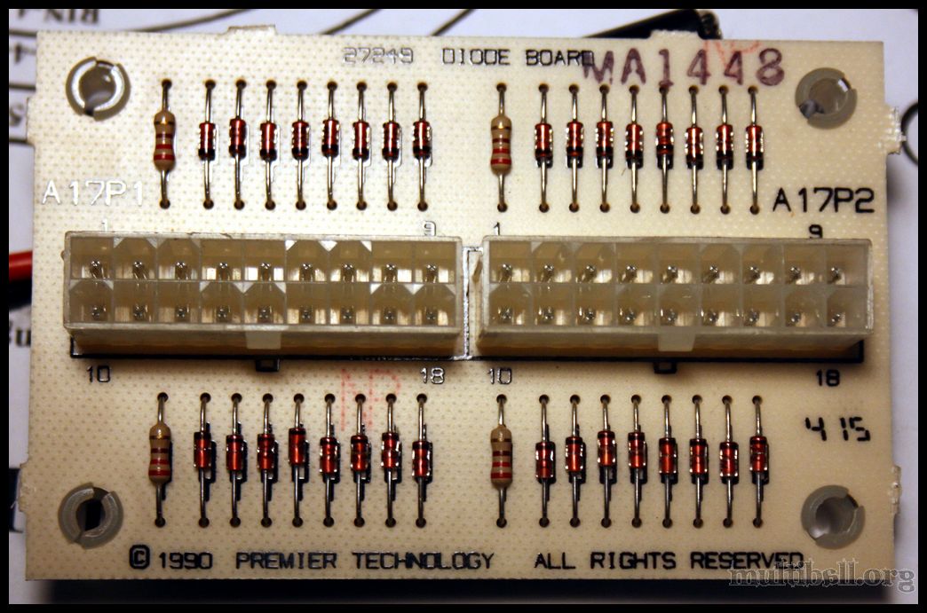
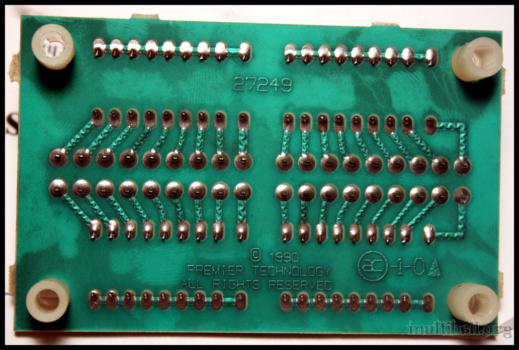
Ok, so you want to check the wire from A3J3 pin 10 and make sure you have continuity from the connector through ALL of the switches. The wire colour code is 411 which is a white wire with a yellow and 2 brown stripes. Use your DMM in continuity test and ring out from the a3J3 connector pin 10 to EACH SWITCH (with the connector disconnected from the PCB) to make sure there are no breaks, and visually inspect each joint and look for any kinks in the wire that may cause intermittent issues. If that all checks out, then test the diode(s) associated with pin 10 of the A3J3 connector using your DMM (this is the A17P1 connector on the diode board), and then also test the 220 ohm resistor tied to that row on the same board. (these have been known to burn up / go open)

Now if all that checks out, this is going to get fun. Sys3 switch matrix shares it's strobes lines with the lamp matrix. (see back to my "fun" comment) What this means is, if everything in the switch matrix is checking out, the source of the issue could be in the lamp matrix. You'll have to check the lamp matrix chart and locate what row of lamps also uses the 'strobe 1' line, and check all of these sockets for a short. Could be a bad bulb, a stray wire but most likely a bad socket coated in organic flux. The factory used solder with organic flux and this tends to be conductive, so you'll have to check for that and there could be flux on a socket that is causing the issue. If you notice any sockets that look at all suspect, try cleaning any / all flux off (with 99% iso, or flux cleaner is best if you have some) and eliminate any shorts.

D
 

tim.sanderson

Active Member
So far I've tested the kickers and slingshots. I get no readings at all.
I just want to make sure I'm doing it right:

I've got my negative in the back side of the connector. (I tested the connection by putting the positive in the other end of the connector to make sure the negative is in right) Should I be testing the switch while it's closed?
I assume it's closed, but I've tried testing both wires connected to the switches, once with each switch closed, once with each switch open. I get no continuity readings either way. I still have to test the pop bumpers.
 

Attachments

  • connector - A3J3 pin 10 - 800px.jpg
    connector - A3J3 pin 10 - 800px.jpg
    60.1 KB · Views: 2,137

tim.sanderson

Active Member
Fingers crossed, I have it working again. After doing what Doug suggested, I couldn't get my DMM to register any continuity between the A3J3 connector and the switches in question. So I traced the yellow/brown/brown wire through the cabinet, and found that it connected to the lamps that light up the modes. (3 lamps on the left side board) I removed the bulbs and tested them. When I put them back into their sockets and fired up the machine I had the slingshots/bumpers/kickers working again. Hopefully I've traced the problem to a flaky bulb or connector/connection. I was premature in thinking I found a fix last time, so I won't go so far as to say it's totally fixed.

It is however, working right now so I'll take advantage and play!
 

Attachments

  • mode lamps 1-3.jpg
    mode lamps 1-3.jpg
    141.7 KB · Views: 2,129

Vengeance

Well-Known Member
Nov 14, 2012
1,990
138
63
Keswick, ON
That seems odd to me that a switch would be tied into the light bulb socket, I can't think of a single game I've ever seen that has done that?
 

Menace

Well-Known Member
Staff member
Nov 14, 2012
2,440
255
83
Santiago de Aurora
Vengeance said:
That seems odd to me that a switch would be tied into the light bulb socket, I can't think of a single game I've ever seen that has done that?

Ahh, but it's not odd. All System3 games share all strobe lines between the lamp AND switch matrix. So every switch matrix row is tied to the exact same strobe line as the lamp matrix row. This is why troubleshooting lamp and switch matrix issues on these games is a royal pain in the ass, because if you're having a switch matrix issue, it could be caused by an issue in the lamp matrix and vise versa.

Good 'ole GTB!

D
 

Menace

Well-Known Member
Staff member
Nov 14, 2012
2,440
255
83
Santiago de Aurora
tim.sanderson said:
So far I've tested the kickers and slingshots. I get no readings at all.
I just want to make sure I'm doing it right:

I've got my negative in the back side of the connector. (I tested the connection by putting the positive in the other end of the connector to make sure the negative is in right) Should I be testing the switch while it's closed?
I assume it's closed, but I've tried testing both wires connected to the switches, once with each switch closed, once with each switch open. I get no continuity readings either way. I still have to test the pop bumpers.

Ok, don't think you're doing it correctly. You got the part about the connector side right as long as your DMM lead is making contact with the pin in the housing at all times. You then take your other DMM lead and touch it to the leg of each switch with the same colour wire (in this case the wht/yel/brn/brn) and "ring it out". If your DMM doesn't beep (ring) then there is a break in the wire between the connector and whatever switch you're testing. These switches are all daisy chained to each other up until the last one in the row (and the last one in the row on paper doesn't mean it's the last one physically in the game)

Hope that helps clear it up a bit.

D