• We have upgaded to the latest version of XenForum and the process finished without any errors!!!! Enjoy the new forum!

Luckydogg's virtual pin project

Luckydogg420

Member
May 12, 2013
825
24
18
Kitchener
I had some time today for woodworking, so I remade the front of the cabinet. Everything is the same, but now the shooter rod is an inch lower. Now it won't hit the tv.

Then I put it all together again, but this time with the glass installed. Here's the piece that I put in front of and behind the tv. The piece in front is about 4" wide but some of it is hidden under the lockdown bar


The rear piece is just under 7" wide and runs from the glass down to the tv bezel. Once everything is painted I think it will look nice.
 

Attachments

  • image.jpg
    image.jpg
    1.5 MB · Views: 1,449
  • image.jpg
    image.jpg
    1.5 MB · Views: 1,448
  • image.jpg
    image.jpg
    1.7 MB · Views: 1,448
  • image.jpg
    image.jpg
    1.7 MB · Views: 1,448

Luckydogg420

Member
May 12, 2013
825
24
18
Kitchener
The button holes in the side rails were to small, so I drilled them out with a stepper bit untill they were the right size for the buttons that I had. The lower buttons feel good where they are.
 

Attachments

  • image.jpg
    image.jpg
    1 MB · Views: 1,448

Luckydogg420

Member
May 12, 2013
825
24
18
Kitchener
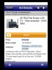
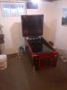
The tv I bought for the backbox was bought used from a local kijiji add. The add had been online for a couple weeks, posted for $150 or best offer. On a whim I sent an email for $100, and they took it.

I went to get the tv, met the couple in their lobby, plugged it in to check that it worked, gave them the cash and left. After getting home and stepping back to look at it I realized that I had bought 37" tv. Not what I wanted.

After thinking it over for a day or two, I traded my 37" with a friend for his 32". Both tv's are RCA. I still get a 32" for $100. He's got a nicer tv. Everyone is happy.


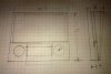
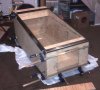
So time to sketch up some back box ideas. I de-cased both tv's to measure what size they were and came up with this.

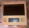
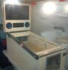
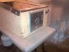
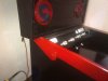
The plan is to miter the corners, dado the bezel, and cut a hole in the bottom. The 17" "DMD" screen will hang down into the main cabinet but i should still be able to fold the top down.

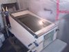
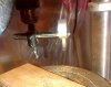
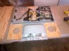
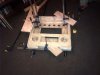
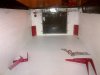
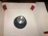
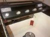
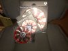
I had to buy speakers for the backbox in order to measure their location and cut the bezel. Their just cheap car audio speakers from our local surplus store. The bezel that I'm making will be one piece for the two screens and speakers. To cut the speaker holes I used a hole bit in the drill press.


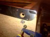
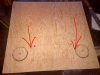
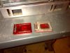
So I measured the bezel out and drilled pilot holes in the corners of the screen location. For the speakers I drilled about half way through the plywood......and it screwed up.

So I got another piece of wood, ran it through the table saw, measured up the bezel, drilled the speakers, drilled pilot holes in the corners of the monitors..............and realized the piece was turned 90 degrees. Making the piece 28 3/4" x 30". Not 30" x 28 3/4" like I needed.

So I stopped for a smoke break. Time to slow down and stop rushing.

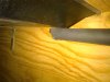
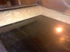
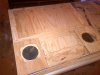
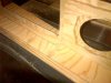
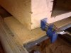
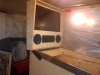
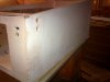
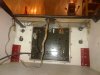
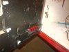
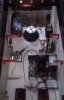
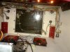
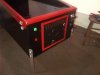
grabbed a third piece of wood, and cut it proper. The backside of the board has been removed with a plunge router, leaving 3/16" of wood on the front to be the bezel.

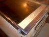
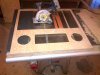
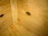
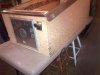
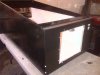
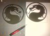
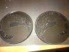
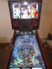
I used a small circular saw to cut out the center hole of each screen and ended up with this

It looks like it will be a nice fit sitting next to the side piece.
 

Attachments

  • image.jpg
    image.jpg
    149.6 KB · Views: 1,444
  • image.jpg
    image.jpg
    1.2 MB · Views: 1,445
  • image.jpg
    image.jpg
    899.1 KB · Views: 1,445
  • image.jpg
    image.jpg
    754.7 KB · Views: 1,446
  • image.jpg
    image.jpg
    130.8 KB · Views: 1,444
  • image.jpg
    image.jpg
    1.5 MB · Views: 1,445
  • image.jpg
    image.jpg
    1.6 MB · Views: 1,444
  • image.jpg
    image.jpg
    1.6 MB · Views: 1,445

Luckydogg420

Member
May 12, 2013
825
24
18
Kitchener
Here's the two upper screens fitted into the bezel for the backbox
 

Attachments

  • image.jpg
    image.jpg
    1.6 MB · Views: 1,426
  • image.jpg
    image.jpg
    807.8 KB · Views: 1,424

Luckydogg420

Member
May 12, 2013
825
24
18
Kitchener
Time to glue things together. I fitted everything together again with the glass installed to double check that everything is square and lined up.

After the cabinet was glued and dried I re drilled the leg bolt holes and installed corner braces behind the leg mounting plates.
 

Attachments

  • image.jpg
    image.jpg
    430 KB · Views: 691
  • image.jpg
    image.jpg
    1.7 MB · Views: 693
  • image.jpg
    image.jpg
    1.6 MB · Views: 692

Luckydogg420

Member
May 12, 2013
825
24
18
Kitchener
Next was gluing the backbox. The 32" tv is slotted into the backbox so that it holds tight in place. I didn't glue the top piece on yet so that the monitor can slide in and out while I'm still building.


I've put two shelves inside the backbox to help keep everything together and better support the 32" tv. Their placed just above the speakers. I didn't get a pic of them but their dadoed into grooves that I added before gluing things together. I also drilled some air vents in the top of the back, and added an access door to the back.
 

Attachments

  • image.jpg
    image.jpg
    1.2 MB · Views: 689

Luckydogg420

Member
May 12, 2013
825
24
18
Kitchener
So now I have two wood boxes... Best put them together and see what it looks like.
 

Attachments

  • image.jpg
    image.jpg
    1.1 MB · Views: 689
  • image.jpg
    image.jpg
    1.8 MB · Views: 691
  • image.jpg
    image.jpg
    1.7 MB · Views: 691
  • image.jpg
    image.jpg
    1.5 MB · Views: 692

Luckydogg420

Member
May 12, 2013
825
24
18
Kitchener
Once the bottom cabinet was dried, I installed corner braces and re drilled the leg bolt holes
 

Attachments

  • image.jpg
    image.jpg
    1.6 MB · Views: 677

Luckydogg420

Member
May 12, 2013
825
24
18
Kitchener
As a side job I spent some time cleaning the coin door. It's amazing how well it cleaned up.

Then I painted some metal bits metallic red
 

Attachments

  • image.jpg
    image.jpg
    1.2 MB · Views: 675
  • image.jpg
    image.jpg
    1.2 MB · Views: 676

Luckydogg420

Member
May 12, 2013
825
24
18
Kitchener
Working back on the bottom of the cabinet, I did a skim coat of wood fill to smooth out the wood grain, so that it won't show through the graphics.

That was sanded smooth and then painted. Black for the outside of the cabinet, white on the inside.
 

Attachments

  • image.jpg
    image.jpg
    1 MB · Views: 678
  • image.jpg
    image.jpg
    1.4 MB · Views: 678

Luckydogg420

Member
May 12, 2013
825
24
18
Kitchener
Yesterday was a great day. I spent a couple hours adding parts. I mounted the subwoofer in the center back of the cabinet. I measured the location, drilled a pilot hole, and then cut it out with a jig saw.


I also installed the front buttons. Start, Exit, and Extra Ball. I plan to wire the one button on the coindoor as insert coin.
 

Attachments

  • image.jpg
    image.jpg
    1.3 MB · Views: 679
  • image.jpg
    image.jpg
    1.5 MB · Views: 678

Luckydogg420

Member
May 12, 2013
825
24
18
Kitchener
Just a few odds and ends here. I mounted the plunger module upside down under the apron.

I also mounted the strobe panels and flasher bar (from Zebulon) on the back panel behind the playfield screen

and I mounted the resistor board (from zeb) inside the cabinet, then soldered up the light bar connections

I also made a bracket with 4 buttons for the service buttons
 

Attachments

  • image.jpg
    image.jpg
    1.3 MB · Views: 629
  • image.jpg
    image.jpg
    1.2 MB · Views: 629
  • image.jpg
    image.jpg
    1.4 MB · Views: 628
  • image.jpg
    image.jpg
    1.1 MB · Views: 628

Luckydogg420

Member
May 12, 2013
825
24
18
Kitchener
It's been very cold here in southern Ontario this month so not a lot has been done.

I bought a couple fans, hopefully this will keep the machine cool


I installed the replay knocker inside the backbox, it just fits behind the 32" tv. The back of the tv is on the right side of this pic and the inside on the back board is on the left. There's about an 1/8" clearance on each side.


I've started placing components inside the bottom cabinet.


And then I spent some time soldering up the connections to the plunger kit and finished the service buttons.
 

Attachments

  • image.jpg
    image.jpg
    1.5 MB · Views: 588
  • image.jpg
    image.jpg
    1.3 MB · Views: 588
  • image.jpg
    image.jpg
    1.1 MB · Views: 588
  • image.jpg
    image.jpg
    1.7 MB · Views: 587
  • image.jpg
    image.jpg
    523.3 KB · Views: 588

Luckydogg420

Member
May 12, 2013
825
24
18
Kitchener
The next step for me is working on the power lines. Hooking up the power switch and complete the wiring. I have a buddy thats an electrician, so it's best to get him over to double check my plan before I move forward. Last thing I want to do is build a fire hazard.

I've started on the computer work. fresh install of windows and begin down loading software. This will be my weak point so I'm following the guide posted by mwong here viewtopic.php?f=29&t=33
 

Luckydogg420

Member
May 12, 2013
825
24
18
Kitchener
I spent some time wiring up the cabinet.

I finished soldering wires together for the strobes and flashers. For the wires that cross the playfield tv I installed a quick connect. This is just a plug for a car trailer hitch lights. It was cheap from a local surplus store.


On the inside left side, I placed the ledwiz with fuse holders (500ma). Although I don't have contactors yet for force feedback this will be perfect to add them later.


Behind that I placed the audio amp.


Along the back wall I placed the power mains. The plug wire comes in here, then runs to the front power switch and back again. There's enough room on the terminal blocks to add extra stuff in the future.


The back right corner has the 2nd pc power supply and zeb's power booster board


And here's the power switch in the normal location. Front right bottom
 

Attachments

  • image.jpg
    image.jpg
    1.6 MB · Views: 534
  • image.jpg
    image.jpg
    1.9 MB · Views: 534
  • image.jpg
    image.jpg
    1.6 MB · Views: 534
  • image.jpg
    image.jpg
    1.7 MB · Views: 534
  • image.jpg
    image.jpg
    1.7 MB · Views: 535
  • image.jpg
    image.jpg
    1.2 MB · Views: 535

Luckydogg420

Member
May 12, 2013
825
24
18
Kitchener
I also worked on the speaker grills. I found a picture online, resized it to proper size, made a mirror copy and printed them on sticker paper


Next, I cut them out with an exacto knife and stuck them on the grills.


Then I grabbed the rattle can and painted them red, to match the rest of the cab


They look better in real life then they do in the pictures, but I'm not 100% satisfied with them. I'll probably touch them up with black paint. Their was some paint bleed under the sticker.
 

Attachments

  • image.jpg
    image.jpg
    869.3 KB · Views: 535
  • image.jpg
    image.jpg
    1.5 MB · Views: 534
  • image.jpg
    image.jpg
    2 MB · Views: 533

Luckydogg420

Member
May 12, 2013
825
24
18
Kitchener
Well the easy part done. The cabinet is built. Time to let my problems shine through. Personally I think the cabinet build is the easy part.

My issues begin with software.


Everything had been dry fitted together earlier so I won't spend a lot of time going through it now. I just reinstalled the screens and turned it on. ....time to play some pinball. ....I mean test for problems.
 

Attachments

  • image.jpg
    image.jpg
    1.4 MB · Views: 532
  • image.jpg
    image.jpg
    1.1 MB · Views: 532
  • image.jpg
    image.jpg
    942.1 KB · Views: 535
  • image.jpg
    image.jpg
    1.2 MB · Views: 536