I've been on a bit of a tear lately repairing piles of boards that I've had sitting on the shelf collecting dust, most of it has been pretty simple stuff, but I thought I would share this one because it was a little uglier than the others.
This is a Data East Level 3 MPU board that I picked up somewhere as a spare for my Back to the Future. This revision of board will work in all DE machines from Laser War to Batman Forever and is essentially the same as a WMS SYS11c mpu.
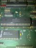
Looking at the picture you can see that someone has replaced one of the 6821 PIA's that had failed at some point in the past. It looks like they did some damage to the board trying to remove the existing chip and tried to patch it back together with a raised machine pin socket to give them access to the traces and solder pads that they damaged. It looks pretty ugly, but surprisingly the board worked like this.
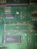
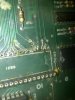
These pictures show the socket cut off and then the solder cleaned from the holes. The worst damage is at the 3rd and 5th pin holes from the left on the bottom row of pins. There are a lot of lifted traces on both the top and bottom of the board, but are mostly intact. I'm going to be replacing the socket I just cut off with machine pin strips, they are not my preferred choice for replacing sockets, but they are the best option for a repair like this to keep from having to possibly run a bunch of jumpers to repair the trace damage.
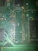
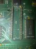
This is the upper machine pin strip installed. At this point I stopped and did a continuity test on each pin of the strip I just installed to make sure that I had a good connection between the board and the strip on both the top and the bottom traces if there were both.
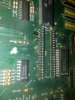
Repairing trace damage on the top side of the board. There are a few different ways you can repair or bypass damaged traces, in this case both traces are broken right close to the chip socket. On the trace in this picture, there is a VIA right next to the socket, so I cleaned out the solder and looped a piece of wire wrap from the VIA to the socket pin hole, you can see the wire in the picture before I pulled it down tight. I used this same procedure to repair the trace at the other hole except there was no VIA and the wrap wire had to be soldered to the trace after the solder mask has been scraped off. Alternately you can use the wrap wire to jumper out the damaged trace and run it from the chip socket pin to the next chip or component in line.
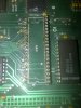
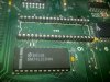
Finally all back together and tested. Like the first strip, once you've got everything soldered test all the pins for continuity. In the first picture you can easily see the repairs I did with the wire wrap. This is a much cleaner repair than what was done previously. Ignore the flux residue, I still have to clean that off.
This kind of trace damage can be pretty easily avoided when removing old chips. When removing old chips, cut them off the board using a pair of flush cutting side cutters and then heat the solder from the top and pull the remaining pin out. Then using a solder sucker or desoldering gun, clean the old solder out of the holes. Do not run your soldering iron any hotter than necessary. Install your socket, check your traces, bam, you're done.
Hopefully this helps someone in the future.")
This is a Data East Level 3 MPU board that I picked up somewhere as a spare for my Back to the Future. This revision of board will work in all DE machines from Laser War to Batman Forever and is essentially the same as a WMS SYS11c mpu.
Looking at the picture you can see that someone has replaced one of the 6821 PIA's that had failed at some point in the past. It looks like they did some damage to the board trying to remove the existing chip and tried to patch it back together with a raised machine pin socket to give them access to the traces and solder pads that they damaged. It looks pretty ugly, but surprisingly the board worked like this.
These pictures show the socket cut off and then the solder cleaned from the holes. The worst damage is at the 3rd and 5th pin holes from the left on the bottom row of pins. There are a lot of lifted traces on both the top and bottom of the board, but are mostly intact. I'm going to be replacing the socket I just cut off with machine pin strips, they are not my preferred choice for replacing sockets, but they are the best option for a repair like this to keep from having to possibly run a bunch of jumpers to repair the trace damage.
This is the upper machine pin strip installed. At this point I stopped and did a continuity test on each pin of the strip I just installed to make sure that I had a good connection between the board and the strip on both the top and the bottom traces if there were both.
Repairing trace damage on the top side of the board. There are a few different ways you can repair or bypass damaged traces, in this case both traces are broken right close to the chip socket. On the trace in this picture, there is a VIA right next to the socket, so I cleaned out the solder and looped a piece of wire wrap from the VIA to the socket pin hole, you can see the wire in the picture before I pulled it down tight. I used this same procedure to repair the trace at the other hole except there was no VIA and the wrap wire had to be soldered to the trace after the solder mask has been scraped off. Alternately you can use the wrap wire to jumper out the damaged trace and run it from the chip socket pin to the next chip or component in line.
Finally all back together and tested. Like the first strip, once you've got everything soldered test all the pins for continuity. In the first picture you can easily see the repairs I did with the wire wrap. This is a much cleaner repair than what was done previously. Ignore the flux residue, I still have to clean that off.
This kind of trace damage can be pretty easily avoided when removing old chips. When removing old chips, cut them off the board using a pair of flush cutting side cutters and then heat the solder from the top and pull the remaining pin out. Then using a solder sucker or desoldering gun, clean the old solder out of the holes. Do not run your soldering iron any hotter than necessary. Install your socket, check your traces, bam, you're done.
Hopefully this helps someone in the future.
Attachments
-
 IMG-20140304-00087.jpg1.1 MB · Views: 168
 -
 IMG-20140304-00088.jpg1.1 MB · Views: 167
 -
 IMG-20140304-00089.jpg1.3 MB · Views: 167
 -
 IMG-20140304-00092.jpg1,007.8 KB · Views: 167
 -
 IMG-20140304-00093.jpg885.2 KB · Views: 167
 -
 IMG-20140304-00097.jpg756.6 KB · Views: 167
 -
 IMG-20140304-00099.jpg1.2 MB · Views: 167
 -
 IMG-20140304-00100.jpg1 MB · Views: 167
 -
 IMG-20140304-00101.jpg1.2 MB · Views: 167