• We have upgaded to the latest version of XenForum and the process finished without any errors!!!! Enjoy the new forum!

LOTR magnet issues...

Pharoah007

Active Member
Nov 17, 2012
260
35
28
Ottawa
I have a question about the Magnet in my LOTR.

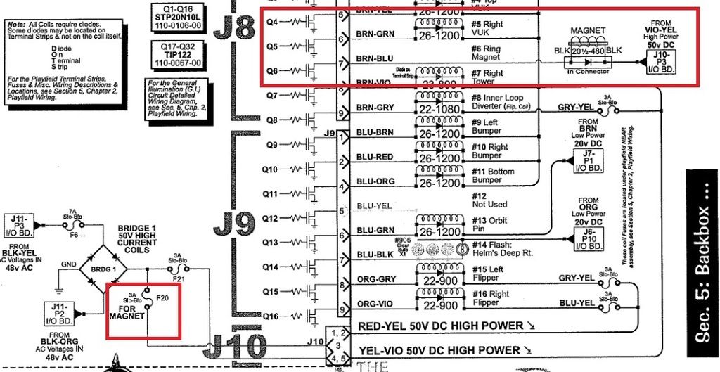
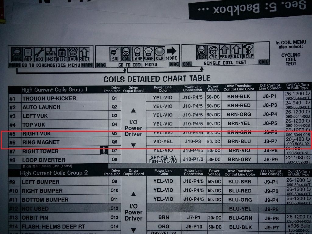
My magnet was blowing fuzes. I swapped in a new PCB with all good transistors and all was well until the magnet fired...then it blew the fuse again. Swapped in a new fuse and it blew right away upon boot up.

I am using a 5A fuse as per the Stern Service recommendation.

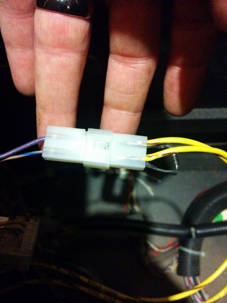
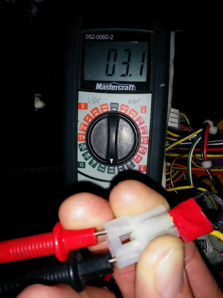
Looked over the magnet wiring and decided to test the diode (remove to test) and the diode tested bad.

Replaced the diode and fired the game up, not the ring magnet "locks on" as soon as I power the game up and will eventually blow the fuze (F20)

Would installing the diode backwards do this? Can a LOTR owner take a picture of their magnet wires (yellow until the connector) and the orientation of the diode that comes out of the connector bridging the 2 outside wires.

Could I have to put in a new Transistor?

thanks.
 

Menace

Well-Known Member
Staff member
Nov 14, 2012
2,440
255
83
Santiago de Aurora
If the diode went bad, it would have killed the FET when it was triggered, so if all you did was replace the diode you only fixed half of the problem. Pull the driver and replace the magnet FET as well, and then check the magnet diode again just in case before re-installing the repaired driver, and you should be good to go. Make sure you use the correct FET!

D
 

Pharoah007

Active Member
Nov 17, 2012
260
35
28
Ottawa
FET = Transistor (IRL540N) correct?

I NEVER had magnet lock on upon start up until I replaced the Diode. I was at the hokey game tonight taking pictures (Sens lost ) and I noticed I had taken a picture of the old diode before I replaced it so I would in fact not put the new one on backwards (assuming the old one was the right way)

When I compare the pic to the way I have the Diode on now...they are the same. what do people here have for diode orientation on their LOTR

IMG_20150419_163745_zpsyzb6rfq4.jpg


I also went ahead and measured the ohms to the magnet.....

IMG_20150419_230004_zpszzc7z4v8.jpg


Can Stern/Sega Transistors be tested while still on the PCB or do I have to remove the transistor to test?
How do I test the transistor...I once knew and have forgotten in my old age.

Bed time, back at this tomorrow.
 

Menace

Well-Known Member
Staff member
Nov 14, 2012
2,440
255
83
Santiago de Aurora
The coil seems to be ok, and the diode likely is too now that you replaced it. The diode is there to protect the MosFET from destroying itself after it turns off power to any coil. If the diode was in fact bad, it would have killed the driving FET, which is apparent now that you are blowing fuses on power up. Just check the manual for the correct orientation of the diode, as it should show you which side the band is associated with vs the wire colour. (you could probably quickly verify by looking at any other coil in the game which way the band should face) But to answer your question, yes if the diode is on backwards you will destroy the drive transistor once the game fires that coil as it will not block the reverse voltage created by the coil when it's turned off.

D
 
Last edited:
  • Like
Reactions: brad808

Pharoah007

Active Member
Nov 17, 2012
260
35
28
Ottawa
To be clear...

I am NOT blowing the fuze upon power up. The magnet is locking on on power up and if I do not turn it off within 5 sec or so, I will blow the fuze. I will dig in the manual for the diode orientation as suggested.

MosFET, FET ?? are these alternate terms for transistors?

EDIT.....

I have included the below video to show the correct function of the 3 switches related to the magnet.


Here is what I found regarding the diode orientation...I have no idea how to read this :(

Untitled_zpsovyyjrrv.jpg


Hopefully this and the below picture with wire colours and diode orientation will help to point me in the right direction.

IMG_20150419_163745_zpsyzb6rfq4.jpg


And some more augmenting information...

IMG_20150420_201350_zpsfcka0e9l.jpg
 
Last edited:

cdnpinballer

Member
Nov 15, 2012
342
13
18
Ok the info from the manual is very useful. It confirms that the orientation of your diode is correct. Band towards the violet wire.

To the left of Q6 the manual reads: Q1 - Q16, STP20N10L, this is the MOSFET you need to replace.

If you replaced/tested the diode and it's good and if the magnet locks on at startup it leads me to believe that the MOSFET is open and needs to be replaced.

I would pull the Power Driver Board and replace Q6 to see if this fixes your problem.
 

Menace

Well-Known Member
Staff member
Nov 14, 2012
2,440
255
83
Santiago de Aurora
As stated, the reason the magnet is locking on is because the MosFET is toast and needs to be replaced. I am going to assume the diode is installed correctly but only because the band is facing the larger AWG wire (which should be the high power feed) as the wire colours used in your game do NOT match the wire colours listed in the manual...

And to clear up your question, a MosFET = FET which is a specific type of transistor, so to answer your question yes it is a transistor. BUT! It's not to be confused with a TIP102 transistor, as it's a compeltely different animal, which is why I always make sure to point out it's a FET vs a transistor.

D
 

cdnpinballer

Member
Nov 15, 2012
342
13
18
Also, the manual is some what unclear about the diode. It says the diode is within the connector but doesn't specify on what side of the connector?

My LOTR has two diode's one on each side of the connector. Perhaps a previous tech realized the diode was bad, left it in place and wired in a new diode on the other side of the connector?
 

Menace

Well-Known Member
Staff member
Nov 14, 2012
2,440
255
83
Santiago de Aurora
The ones used in Stern games are MosFET = Metal-oxide-semiconductor Feild Effect Transistor. It's basically a transistor that can be driven at logic level, whereas a TIP102 is a darlington NPN transistor and requires more to drive it, which is why you have the pre-drive 2n5401 transistors on WPC games.

D
 

Menace

Well-Known Member
Staff member
Nov 14, 2012
2,440
255
83
Santiago de Aurora
Also, the manual is some what unclear about the diode. It says the diode is within the connector but doesn't specify on what side of the connector?

My LOTR has two diode's one on each side of the connector. Perhaps a previous tech realized the diode was bad, left it in place and wired in a new diode on the other side of the connector?

Yeah, that is likely the case...

D
 

Menace

Well-Known Member
Staff member
Nov 14, 2012
2,440
255
83
Santiago de Aurora
To the left of Q6 the manual reads: Q1 - Q16, STP20N10L, this is the MOSFET you need to replace.

Just for reference, don't bother replacing Q6 with the STP20N10. (for reasons I'm not going to get into here) Just use the recommended IRL540N replacement, as this is a much more robust part.

D
 

Pharoah007

Active Member
Nov 17, 2012
260
35
28
Ottawa
Thanks all.

I will replace Q6 with a IRL540N as soon as I find some time.

question... could the member with 2 diodes on his magnet wires have 2 diodes as a form of X2 redundancy ?? so if 1 diode blew, the 2nd would take its place?? or do diodes blow "open" so X2 redundancy would not work.

I will keep everyone informed on my progress, thanks again.
 

Pharoah007

Active Member
Nov 17, 2012
260
35
28
Ottawa
the wire colours used in your game do NOT match the wire colours listed in the manual...
D

Just to clear this up for future searches by anyone having this problem...

The "purple" wire in the PIC is in fact violet with yellow stripe.
 

Menace

Well-Known Member
Staff member
Nov 14, 2012
2,440
255
83
Santiago de Aurora
Just to clear this up for future searches by anyone having this problem...

The "purple" wire in the PIC is in fact violet with yellow stripe.

But the manual claims the other wire is brown-blue, but yours is yellow-blue. :) The good thing is you cna always tell which wire is the high-poewr for coils as it's usually the larger AWG.

D
 

Pharoah007

Active Member
Nov 17, 2012
260
35
28
Ottawa
But the manual claims the other wire is brown-blue, but yours is yellow-blue. :) The good thing is you cna always tell which wire is the high-poewr for coils as it's usually the larger AWG.

D
The brown-blue is right beside the violet yellow, on the same side of the connector. The yellow wires on the right of the pic go to the magnet.