• We have upgaded to the latest version of XenForum and the process finished without any errors!!!! Enjoy the new forum!

GTB Raven sound issues

Topher5001

Member
Oct 12, 2016
46
0
6
57
Canada
So, now that the game's playing correctly, it's time to get back to the sound.
After it got fixed, there'd be no sound for a couple hours & then the gameplay music would play constantly. Then odd sounds would start, like the explosion sound would start & then become constant. Turning it off & then on or pressing the reset on the soundboard would make it stop, but it would eventually return. No sounds would play during switch hits or when starting the game or when it counted bonus.
Last night the music started, but it would also play the machine gun sound when it spells Raven at the start of the game & when counting bonus. Surprisingly, it would also play sounds when switches were hit. Maybe not all switches & maybe not the correct sounds; I'll have to watch a gameplay video to refresh my memory. It definitely played sounds that didn't belong. Plus, the gameplay music kept playing beneath the sounds. Switching it off & on & pressing the SB reset wouldn't stop it this time though.
The tech (Al) was going to try to find a soundboard to try in it, but now I'm not sure it's the SB. He's a half hour to 45 minutes away & I don't want to get him here if it's not. I was new to electronic troubleshooting & repair back when this started & I messed with the A6P1 connector with the game on. Would this corrupt the sound proms? I'm leaning this way. I honestly don't think it's a connector, but it may be the driver board too.
 

Menace

Well-Known Member
Staff member
Nov 14, 2012
2,440
255
83
Santiago de Aurora
This is all related to connector pins, and based on the erratic behaviour you have described this sounds like classic connector pin issues. If the game has not had all of the connector pins replaced, this is a MUST DO before you begin chasing your tail around in circles. The majority of issues with any GTB solid state game usually comes down to bad connector pins... everything used from the factory was garbage.

So, start there and once you know all the pins are good you can then begin to actually troubleshoot any remaining issues.

D
 

Topher5001

Member
Oct 12, 2016
46
0
6
57
Canada
Hi Menace.
I've re-pinned A1J1, J2, J5 & J6; A2J2, J4, J5 & J6; A5P1 & A6P1. I added the 5v DC & logic ground to the harness between the MPU & driver board. I don't have enough bifurcated crimps to do the double-sided connectors.
I checked the connectors & they look good, but I'll double check.
 

Menace

Well-Known Member
Staff member
Nov 14, 2012
2,440
255
83
Santiago de Aurora
Yeah, where GTB actually sends most of the sound triggers from the MPU through the driver PCB you'll have to get the double-sided ones done too. It's easier to just buy that harness pre-done... and if I could remember the name of the company I would post it here for you. Brain cramp...

Big Daddy does it (although that isn't the company I was thinking of);
http://www.bigdaddy-enterprises.com/harnesses/harness-index.htm


D
 
  • Like
Reactions: sylvain

sylvain

Active Member
Apr 27, 2013
209
75
28
Ottawa, ON
You were probably thinking of Docent Electronics:
http://www.docentelectronics.com/httpdocs/AmusementGames/Pinball/Gottlieb/system 80 AB.htm

I have bought a few System 1 & System 80 MPU-Driver and power-supply-MPU harnesses from them years ago...

Yes, the sound addressing leaves the MPU, to the driver board via 4 wires within the large MPU-Driver harness. Then, one chip on the driver board (Z13 inverter) sends the drive output via driver board connector A3-J5, to the sound board A6-J1 input.

Did you confirm all proper supply voltages arrive on the sound board as well?

- Sylvain.
 
Last edited:

Topher5001

Member
Oct 12, 2016
46
0
6
57
Canada
On A6P1 pin 13 I get -6.4v DC (should be -12v); pin 14 12.9v DC (12v) & pin 15 I get 4.5v DC (5v).
I was looking at the Docent kit. It looks like it's wires with crimps. I guess you re-use the housing? How hard is that?
I have bifurcated crimps, but not enough to do the whole connector.
 

Menace

Well-Known Member
Staff member
Nov 14, 2012
2,440
255
83
Santiago de Aurora
If you've only got -6.4V where it should be -12 that's an issue for sure. That sound PCB will need a good -12 / +12 / +5 to work. (the 4.5v you have *should* be ok)

D
 

Topher5001

Member
Oct 12, 2016
46
0
6
57
Canada
I'll have to check were that comes from. I set the 5v PS to 5.05v at the MPU with everything hooked up so I don't understand why there's a voltage drop.
 

Menace

Well-Known Member
Staff member
Nov 14, 2012
2,440
255
83
Santiago de Aurora
Did you set the 5V with all the PCB's connected? If you didn't have everything connected the power supply had no load which is why it's lower with everything connected.

D
 

Topher5001

Member
Oct 12, 2016
46
0
6
57
Canada
Yeah, that's what I was thinking too. I'll double check my re-pinning on the single sided connectors & try to trace back where the voltage comes from to see if I need to work on the double-sided ones. I've only got about 40 bifurcated crimps though.
 

Topher5001

Member
Oct 12, 2016
46
0
6
57
Canada
Got around to checking voltages on A5, the aux. power supply.
Pin 5 = -6.53v DC (-12v DC)
Pin 7 = 7.1v AC (12v AC)
Pin 10 = 12.75v DC (12v DC)
I also checked pin 6, the 12v AC input & got 7.3v AC. So this means the problem's not on A5 but on the transformer panel, correct?
Looking at the schematics, it comes from fuse F1. There's nothing else in the path until A12J6/A12P6. I guess it would be a good idea to reflow the solder on the pins & re-pin the connector. What do I use for that? I have a bunch of Molex trifurcons & bifurcated crimps. Do the old crimps come out the same way as on the single-sided connectors?
Edit: Should I disconnect A12J6 & check continuity to A5P1?
 
Last edited:

Menace

Well-Known Member
Staff member
Nov 14, 2012
2,440
255
83
Santiago de Aurora
Before you go re-pinning try unplugging and re-plugging all of the connectors in between the transformer and the PCB, you might find that the wiping motion of this action will bring the voltage up to spec. If this works, then you have verified the connector needs to be re-pinned.

Alternatively you can measure the voltages at the transformer before anything goes through a connector to verify as well.

D
 

Topher5001

Member
Oct 12, 2016
46
0
6
57
Canada
I've had the transformer out a few times to replace the rectifiers & add posts for the ground mods with no change. I'll check the voltages coming out of the transformer & go from there.
 

sylvain

Active Member
Apr 27, 2013
209
75
28
Ottawa, ON
Got around to checking voltages on A5, the aux. power supply.
Pin 5 = -6.53v DC (-12v DC)
Pin 7 = 7.1v AC (12v AC)
Pin 10 = 12.75v DC (12v DC)
I also checked pin 6, the 12v AC input & got 7.3v AC. So this means the problem's not on A5 but on the transformer panel, correct?
Looking at the schematics, it comes from fuse F1. There's nothing else in the path until A12J6/A12P6. I guess it would be a good idea to reflow the solder on the pins & re-pin the connector. What do I use for that? I have a bunch of Molex trifurcons & bifurcated crimps. Do the old crimps come out the same way as on the single-sided connectors?
Edit: Should I disconnect A12J6 & check continuity to A5P1?

What AC voltage do you measure actually, if you put one probe of your multimeter on pin 6 and other probe on pin 7 ?
Hopefully it will be close to 12V AC - as expected for this circuit (as opposed to measure each pin compared to ground).

Pin 5 measured voltage does appear way too low - either there is a bad or open CR1-CR4 diode or cold solder joint on the Aux
power supply, or bad C7, R7 or VR1, or the circuit using this -12V is draining too much current.

- Sylvain.
 

Topher5001

Member
Oct 12, 2016
46
0
6
57
Canada
Hi Sylvain.
Checked the AC between pins 6 & 7 & it's 13.1v. I'll read up on checking diodes, resistors, etc., & look for cold solder joints.
 

Topher5001

Member
Oct 12, 2016
46
0
6
57
Canada
Since the reading between pins 6 & 7 seem okay, I guess CR1 thru CR4 are good. I was going to check the cap, resistor & Zener diode on the circuit so I read up on how to check them. The cap needs an ESR meter & the resistor needs to be taken out of circuit, but I don't have the equipment or experience to do this. Should I just have them replaced? I can't imagine it would be too expensive.
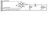
I've attached a picture of the circuit schematic.
Oh, could someone please explain what the different components in this circuit do? I'm guessing the cap provides a constant voltage & the resistor drops the -14.5v to -12v, but I don't know what the Zener diode does, or how the cap or diode work with them going to ground.

Thanks!
 

Attachments

  • A5 Circuit.jpg
    A5 Circuit.jpg
    32.7 KB · Views: 7
Last edited:

sylvain

Active Member
Apr 27, 2013
209
75
28
Ottawa, ON
You have proper AC voltage at the input of the four diodes bridge - it does not prove that the diodes are good.
Yes, the C7 electrolytic capacitor smoothes the rectified pulsing DC out of the four diodes.

What voltage do you measure between ground and one side of R7? What about the voltage between ground and the other side of R7 ?

With the power OFF, you should be able to measure the four diodes individually with your multimeter in diode test mode.
You should also be able to measure R7 with your multimeter in resistance (ohms) mode - even if in-circuit.
It might measure lower than 100 ohms if good, due to the other components in the circuit. But, it should not measure much higher than 100.
You can disconnect the connector to the aux power supply to see if it makes a difference in the diode test and resistor measurement test.

The R7 resistor is there to limit the current (and also drops the voltage across it from -14.5 to -12.0 volts).
The zener diode regulates the voltage to -12V, e.g. it will conduct current reverse through it so that there will be always -12V
compared to ground - if the diode is good - regardless what voltage is initially arriving on R7.
There are easy-read web sites describing what is a zener diode and what it does.

So, the low -12V voltage at pin 5 of the connector might be due to a bad diode, open capacitor, open or drifted R7, bad VR1.
Or, the sound board drawing too much current on its -12V input coming from the aux power supply...

- Sylvain.
 

Topher5001

Member
Oct 12, 2016
46
0
6
57
Canada
Thanks Sylvain! Great info.
I'm new to this & am really enjoying learning it. I had read on Terryb's website, pinballrehab, about the different components & how to test them. It said the zener diode allows voltage to pass in one direction unless the voltage reaches a certain point & then it flows both ways, but I didn't know what the purpose was in this circuit.
I was thinking last night that I should be able to test R7 like you said. I'll test the diodes & measure R7 tonight.